Frequency shifting almost demystified
Frequency shifting is similar to ring modulation, but produces only an upper or a lower spectral side-band whereas ring modulation produces both side-bands. If the frequencies in the input signal are $f_k$, then the output frequencies shifted by $\sigma$ Hz are $f_k \pm \sigma$ Hz.
Ring modulation with a sinusoid carrier can create a very dense spectrum because it introduces new partials symmetrically around the carrier, so the number of partials doubles.
Since frequency shifting (a.k.a. single side-band modulation, SSB) only shifts the partials that are present in the sound, it does not increase the number of partials. Therefore it may sound a bit hollower or smoother than ring modulation.
If the input sound is harmonic, a frequency shift will alter the ratios of the partials and make the sound inharmonic, unless the shift amount is equal to the frequency of one of the harmonic partials in the original sound.
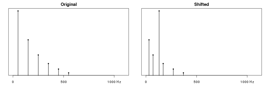
Downshifting may result in negative frequencies. But there is no way of telling if an observed frequency in a signal is positive or negative, so a negative frequency will just flip sign and become positive. For example, suppose the original sound has partials at 50, 150, 250 and 350 Hz. Shifting this signal down by 180 Hz gives new partials at -130, -30, 70 and 170 Hz. Since negative frequencies are just mirrored into positive, the new spectrum has partials at 30, 70, 130 and 170 Hz.
A bandlimited spectrum with some highest frequency $f_h$ can be mirrored so that high frequencies become low and vice versa by shifting it down by a frequency greater than $f_h$.
Shifting by an analog module
Cwejman's FSH-1 eurorack module can be used in two modes: either as a ring modulator or as a frequency shifter. It has two audio inputs, one of which has an attenuator, and three audio outputs: upper and lower side-bands, and a mixed output with a knob as well as a cv input that controls the balance of the "up" and "down" signals sent to the mix output. There are also two cv inputs for the amount of frequency shift, one with an attenuator and one calibrated to the 1V/oct standard.
Self-oscillation
Although its purpose is to process incoming signals, it may be interesting to observe that under certain conditions the module can be made to self-oscillate if patched so that its output feeds back to its input.
First feedback example: the module is set to low frequency range (slow modulation) and frequency shifting. The mix output is patched back to the audio input II (without attenuator). The stereo output signals that we hear come from the up and down outputs. In the first half, the mix knob is turned 100 % up; in the last half it is turned 100 % down.
Self-oscillation 1: Slow frequency shift.
Self-oscillation can also be demonstrated in the ring modulation mode. Here the coarse carrier knob is swept from its lowest to highest frequency.
Self-oscillation 2: Ring modulation, audio range, carrier swept.
Sound processing
The following sound examples illustrate the sound processing capabilities using two recordings. First, here are the original recordings.
Original noisy field recording: kids playing on the street.
Original piano recording: excerpt from Les tendres plaintes by Rameau.
∿∿∿
Since it is already sacrilegious to play Rameau on a modern piano instead of a harpsichord, it cannot possibly get much worse by shifting its frequencies a bit, can it? The three following examples demonstrate ring modulation, then frequency shifting down and up, in all cases with the carrier set to 440 Hz.
Rameau ring modulated, carrier = 440 Hz.
Rameau frequency shifted down by 440 Hz.
Rameau frequency shifted up by 440 Hz.
Frequency shifting with a low frequency carrier can be used for interesting spatial effects if the up and down signals are sent to the left and right channels, respectively. Almost the same effect can be achieved by ring modulation; the difference between frequency shift and ring modulation is a subtle one.
Spatial effects by slow-paced frequency shift.
Spatial effects by slow-paced ring modulation.
As can be heard, the spatial effects are most prominent with the noisy recording in the first part of these examples.
∿∿∿
The FSH-1 module tends to impose its own signature on sounds with spiky impulses in the form of a ringing tone at the carrier frequency. This resonance is stronger with frequency shifting than it is with ring modulation, and can be most easily noticed when the input signal is a sub-audio waveform with discontinuities, such as a square wave.
In the next two examples the coarse carrier knob is swept from high to low frequencies in the audio range; the input is an LFO square wave. The first example uses frequency shifting and the second one ring modulation.
Pinging by square wave in frequency shift mode.
Pinging by square wave in ring modulation mode.
There are many other things that can be done with the frequency shifter, some of which will be mentioned below. An expensive analog module is not necessary for any of them, since frequency shifting can be done on digital signals as well.
Frequency shifting in the digital domain
Single side-band modulation is really not much more than a few clever tricks with trigonometry. All that is needed is the input signal and a phase shifted copy of it, and a quadrature oscillator which is just the complex exponential signal $e^{i\omega t} = \cos (\omega t) + i \sin(\omega t)$.
Using Csound
Various effects can be easily implemented in Csound using the hilbert opcode for phase shifting of the input signal. The tricks used can be gleaned from the following Csound instrument definition.
instr 1 ; SSB-modulation

 ain		soundin		"rameau.wav"	; original sound to be shifted
 isq2		=		1.0 / sqrt(2.0)

 are, aim	hilbert		ain
 amodre		oscili		1, p4, 1, 0.0	; modulator in sine phase
 amodim		oscili		1, p4, 1, 0.25	; modulator in cosine phase

 a1		=		are*amodre
 a2		=		aim*amodim

 adown		=		isq2*(a1 + a2)
 aup		=		isq2*(a1 - a2)

		outs		adown, aup

endin
And what does it sound like? In fact, not so different from what can be done with an analog module. This comparison is again of the Rameau piece shifted up and down by 440 Hz, the up and down parts going each to its own channel.
Rameau shifted 440 Hz up and down by Cwejman.
Rameau shifted 440 Hz up and down by Csound.
It should be noted that the sound is extremely sensitive to minuscule variations in the amount of shift. In part this sensitivity has to do with how partials collide or not, reinforcing or cancelling out. Another reason is that the frequency shift alters the harmonicity of the sound.
The sound examples using the FSH-1 module were made after carefully calibrating the carrier frequency by ear—by listening to beats against a fixed reference tone. However, the small differences that can be discerned between the two sound examples are most likely caused by factors other than a mismatch of carrier frequency. Csound does sound different than Cwejman, but which one you prefer is a different matter.
The interesting thing with the hilbert opcode is that it uses two matched IIR allpass filters with a 90° phase difference between its two output signals across a wide band of frequencies. But there is another way to produce the same phase difference using two FIR filters.
An implementation with FIR filters
The derivation of a FIR filter Hilbert transformer can be found in many DSP textbooks. The Hilbert transform takes a real-valued signal $x(t)$ and turns it into a 90° phase-shifted version of itself. For example, if $x(t) = \cos(t)$, then its Hilbert transform is $\hat{x}(t) = \sin(t)$. The corresponding analytic signal $x_a \in \mathbb{C}$ is formed by making a complex valued signal where the real part is the original signal and the imaginary part is the phase shifted version: $x_a = x + i \hat{x}$. So again, if $x(t) = \cos(t)$, then the analytic signal is $\cos(t) + i \sin(t) = e^{it}$.
Let $ w(t) = e^{i \omega t} $ be the complex carrier signal and $x(t) \in \mathbb{R}$ the signal to be processed. The Hilbert transform is carried out by the convolution $\hat{x} = x * h$, where $h$ is the impulse response of the filter. The frequency-shifted signals are then obtained by multiplying the analytic signal with the carrier and taking the real part of the product. In other words, the up-shifted and down-shifted outputs are given by $$ x_{up} = \Re (x_{a}w) $$ $$ x_{down} = \Re (x_a \bar{w}) $$ where $\bar w$ means the complex conjugate of $w$.
It is easy to check by carrying out the multiplications and separating the real and imaginary parts that this complex multiplication is equivalent to the code in the Csound instrument above. The substantial difference between this implementation of SSB using a FIR filter and the one in Csound is that the latter instead uses a matched pair of recursive (IIR) filters. The FIR filter needs to be relatively long, which means that it becomes inefficient as well as introducing a latency. For these two reasons, a recursive filter may often be preferred.
Since SSB works by phase cancellation of the partials in the suppressed side band, small errors will result in less than perfect phase cancellation. Therefore, when shifting a sinusoid from $F$ Hz up to $ F + \delta $ Hz, the lower side band at $F - \delta $ Hz will be weakly present in the signal.
Using the FIR version, the filter's coefficients are the bi-infinite sequence $$ h_n = \begin{cases} 2 \over {\pi n} & \mbox{for odd } n \\ 0 & \mbox{otherwise} \end{cases} $$ which has to be truncated and made causal. In other words, one selects a segment of $2N+1$ filter coefficients $h_n$ for $-N \leq n \leq N$ and shifts the segment by $N$ samples so that it begins at index 0. Then the real part of the analytic signal also has to be delayed by $N$ samples so that it is properly aligned with the imaginary part.
Simply truncating the infinite sequence is not a very good solution, since this is equivalent to using a rectangular window. And it turns out that a badly designed filter has consequences for the side-band suppression. Using, say, a Hamming window can improve the side-band suppression by about 18 dB as compared to a rectangular window.
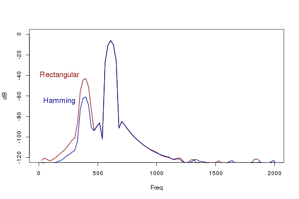
Windowing the impulse response with a Hamming window improves side-band suppression as compared to a rectangular window.
Comparisons
The impulse responses of Csound's hilbert opcode are shown in the figure:
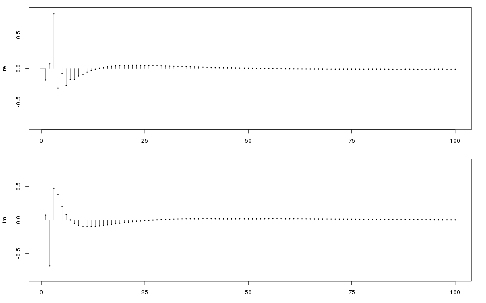
The real and imaginary parts of the impulse response of the Csound opcode hilbert.
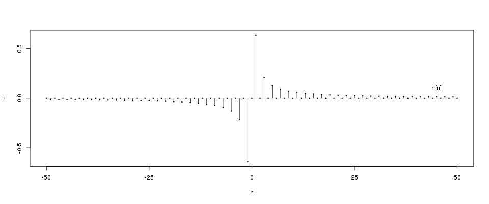
The impulse response of the unwindowed FIR filter.
The recursive filter realisation is certainly more efficient than a FIR filter of equal performance. However, although lots of filter coefficients would normally be required for the FIR Hilbert transformer, since all the even coefficients are zero and because of the odd symmetry, only a quarter of the multiplications for a length $N$ FIR filter is actually needed.
Miscellaneous tricks with frequency shifting
Regardless of whether the frequency shifting is carried out with analog circuits or by digital algorithms, the same tricks can be applied with comparable results.
- Feedback. One of the output signals is mixed in with the input. Used in the so called barberpole phaser effect.
- As already demonstrated, the signal can be spatialized by slow-paced modulation.
- The shift amount can be time-variable. If the shift amount is controlled by the output of an oscillator it results in a kind of FM which produces a dense spectrum.
- Using a harmonic input sound and shifting it by an integer multiple of its fundamental frequency yields another harmonic sound, but with a different timbre.
- The output may be a mixture of the down and up signals. Modulating the balance of these two components leads to effects that are more similar to AM.
- The signal may be first shifted up and processed by a comb filter (or delay), then shifted back down. The result will be a kind of inharmonic comb filtering.
Furthermore, the digital implementations allow the real and imaginary parts of the shifted signals to be output separately. Since these signals are 90° out of phase with respect to each other, this too can be a way of giving a mono signal a broader stereo image.
Further reading
J. Ville: Theorie et applications
de la notion de signal analytique. Cables et Transmissions, 1948.
Classic paper that lays the foundations.
S. Wardle: A Hilbert-Transformer
Frequency Shifter for Audio. DAFx 1998.
Briefly discusses some musical effects.
S. Sangwine and N. Le Bihan:
Hypercomplex Analytic Signals:
Extension of the Analytic Signal Concept to Complex Signals. 15th European Signal Processing Conference, 2007.
The usual complex-valued analytic signal is associated with a real-valued signal, but this paper tries
to see what happens if one makes an analytic signal corresponding to an already complex-valued signal.
It does not answer the question whether this extended analytic signal must live in the space of
complex-valued quaternions (biquaternions, which are represented by 8 real numbers) or if ordinary quaternions
(using 4 real numbers) are sufficient.
Clay Turner: An Efficient Analytic Signal Generator.
IEEE Signal Processing Magazine [91] July, 2009.
Another FIR-based approach.
H. Olkkonen, P. Pesola and J. T. Olkkonen:
Computation of Hilbert Transform via
Discrete Cosine Transform. Journal of Signal and Information Processing, Vol. 1 No. 1, 2010.
Explains how to do it with the FFT or DCT.
© Risto Holopainen 2016